


The Trigger IO extension is an upgrade for the LXR drumsynthesizer that provides additional analog trigger in- and outputs. It has
The outputs are V-triggers, but can also be modified to S-triggers for vintage gear with some additional parts (not included in the kit)
This assembly guide only covers the more common V-Trigger assembly.
The BOM is available here
Schematic can be found here
This section gives a short overview over the functionality of the expansion board.
The 7 trigger out jacks generate a short +5V pulse signal whenever a note is played on the corresponding sequencer track.
This output is high whenever the sequencer is stopped. you can use it to reset connected external sequencers when the LXR is stopped.
A high level on this input will stop and reset the LXR sequencer.
A low level will restart the sequencer.
These outputs will generate a continuous clock signal while the internal sequencer is running.
There are 4 parameters at the end of the global settings
menu to controll the trigger IO settings.
Press shift + load/save to enter the settings menu.
Scroll to the right with the encoder until you see the 4
parameters "cki, co1, co2 and mod"
co1 = clock out 1, co2 = clock out 2 ppq settings.
On this page you can set different prescalers for the clock
outs.The tempo can be set to 1, 4, 8, 16, or 32 pulses per
quarter note.
If the BPM is set to zero (external sync) you can use this
input to sync the sequencer to an external clock.
The input also has a prescaler on the trigger settings page
and can be set to 1, 4, 8, 16, and 32 ppq.
The parameter is named "cki = clock in ppq"
The 'mod' parameter controls the gate mode. Per default
the trigger IO outputs just short 5V pulses.
If the gate mode is turned on, the trigger pulse will be high
as long as the amplitude envelope is bigger than 0 - i.e as
long as a sound is playing.
The first step is to solder the resistors. The 10k resistors on the bottom of the PCB are only needed for S-Triggers and can be left unpopulated.
|
Image |
Description |
Amount |
Notes |
|---|---|---|---|
|
|
1k resistor |
20 |
|
 |
100k resistor | 2 | |
 |
1M resistor | 2 | |
 |
10k resistor | 2 |

You should have plenty of cut off resistor legs left from the previous step. Use them as wire bridges to populate the 10 V-/S-Trigger selection spots on the PCB. Insert them in the right V-Trig position.
|
Image |
Description |
Amount |
Part nr. |
Notes |
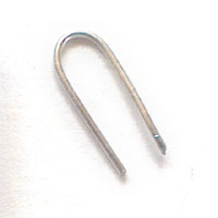 |
Wire Bridge | 10 | - | This is just a normal piece of wire. use one of the cut off resistor legs from the previous steps. |

Solder the jacks to the PCB. The washers and nuts are not needed.
|
Image |
Description |
Amount |
Notes |
|---|---|---|---|
|
|
3.5mm Audio Jack |
12 |
|

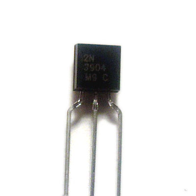
Solder the 12 transistors to the marked spots. The other transistor places on the PCB can be left blank, as they are also only needed for the S-Trigger mod.
|
Image |
Description |
Amount |
Notes |
|---|---|---|---|
|
|
2n3904 Transistor |
12 |
Watch out for the right orientation! Align the flat side of the transistors with the flat marking of the silkscreen. |
![]()
![]()
|
Image |
Description |
Amount |
Notes |
|---|---|---|---|
|
|
14 pin keyed header |
2 |
The slot has to face to the PCB edge to ensure the right polarity. |

Solder the 2nd connector to the bottom of the LXR frontpanel board. There is a header marked "Trigger Extension" (from rev. 0.5 and up). Once again the slot in the header has to point to the edge of the board

|
Image |
Description |
Amount |
Notes |
|
|
Electrolytic
capacitor
|
1 |
Polarized part! The shorter leg is negative, the longer leg is for the positive voltage. |

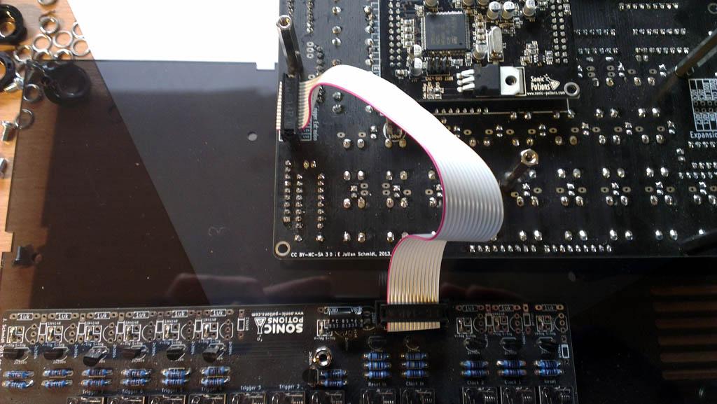
use the ribbon cable to connect the trigger IO PCB to the LXR frontpanel trigger extension port.
If you have a Batch 1 board (rev0.4 without round corners) the Trigger Extension Header on the PCB is missing. Please read the next step to learn how to wire up the board.
|
Image |
Description |
Amount |
Notes |
|---|---|---|---|
|
|
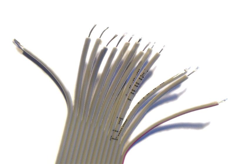
ribbon cable with 14 pin connector |
1 |
|
The cable has 2 connectors.
The one with the 'nose' from the keyed header pointing away
from the cable is for the frontpanel PCB:

the side with the 'nose' pointing to the cable is for the trigger PCB:

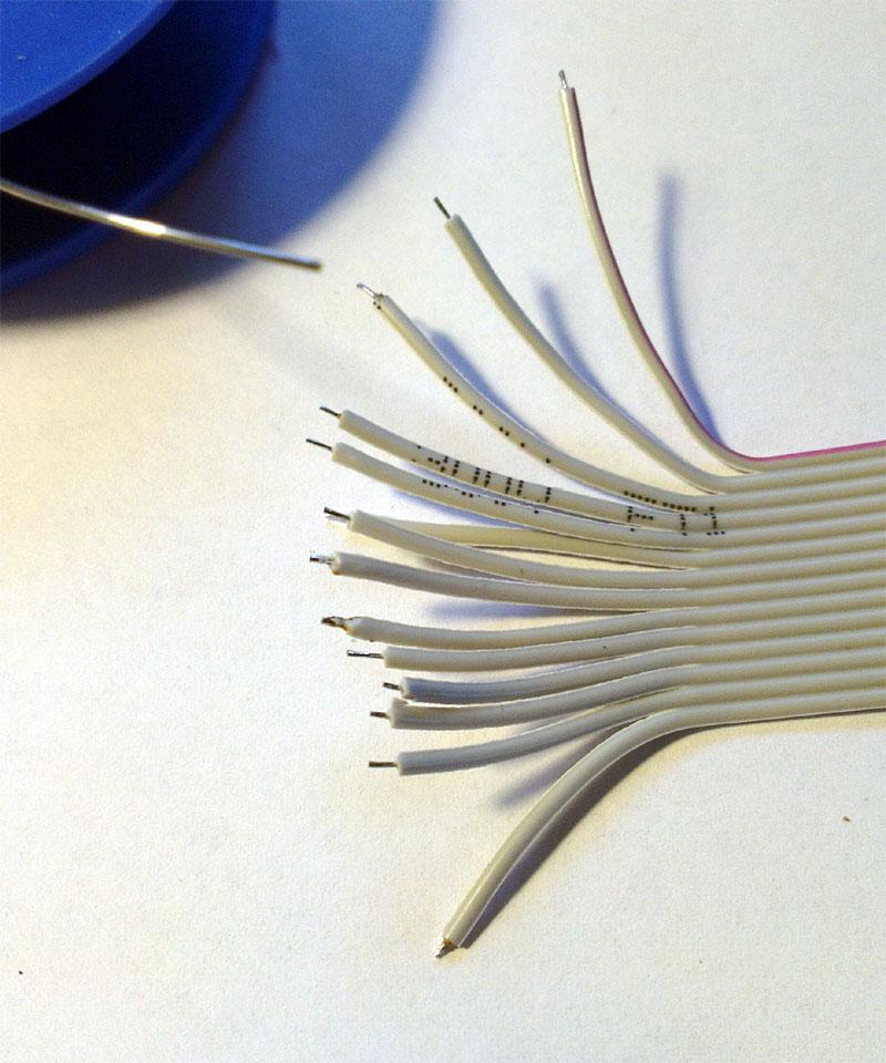
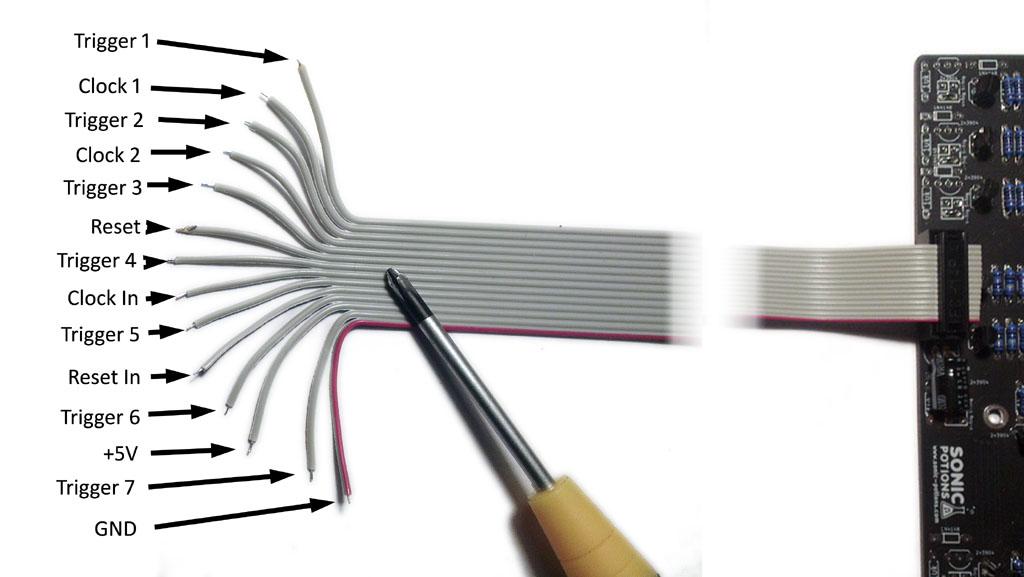
This step is only needed for user that have an early batch 1 board without the trigger IO expansion header. If you have the header on your board, please skip this step.
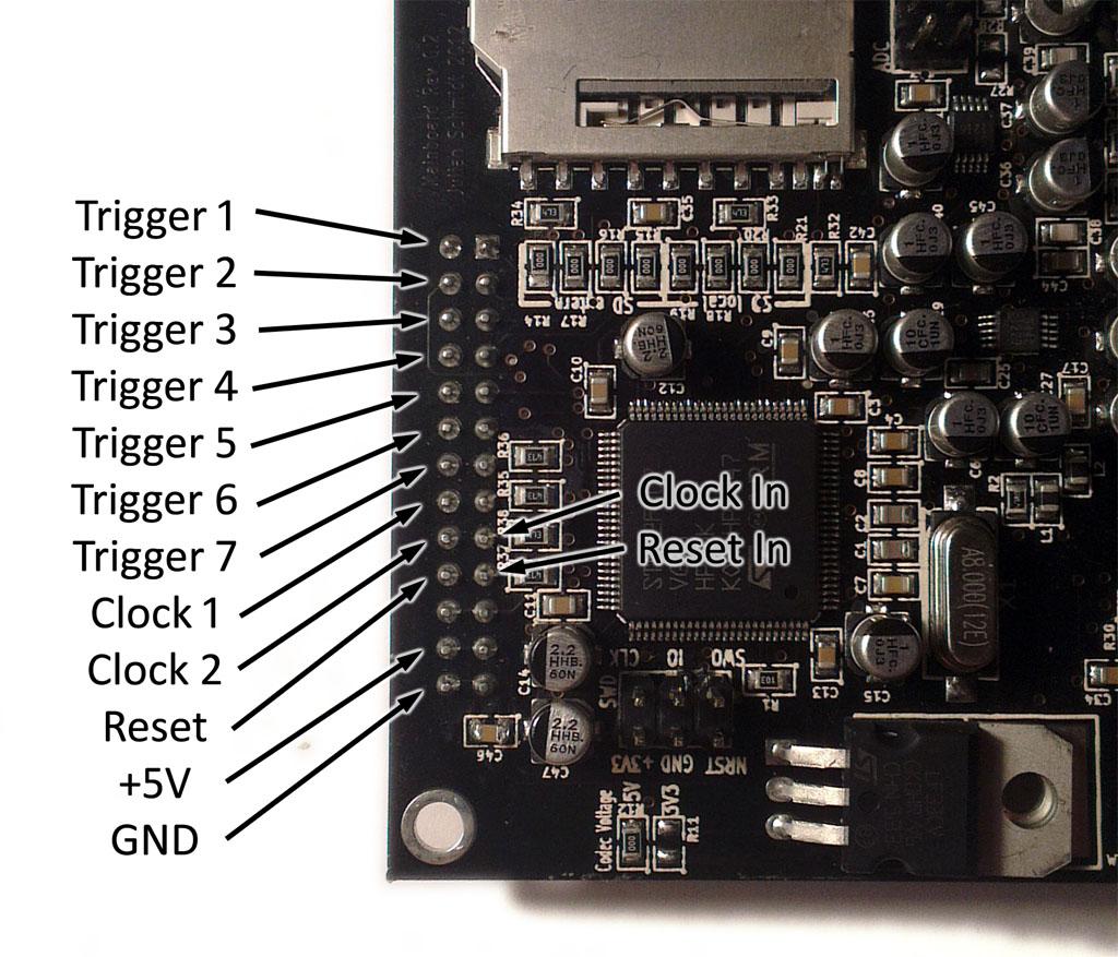
Since there is no trigger IO expansion header on the frontpanel board, you have to solder the cable directly to the mainboard connector.


Before you assemble the Enclosure, it is advised to test the trigger board. It's quite annoying to spot a mistake after assembling the case!
First remove the ribbon cable from the trigger PCB. This makes the assembly easier.
Put the 3 screws through the holes indicated on the image and add 3 plastic washers to each screw from the top.
|
Image |
Description |
Amount |
Notes |
|---|---|---|---|
|
|
10mm M3 screw |
3 |
|
 |
plastic washers |
9 |

Put the PCB on top of the washers and screw the new 27mm standoffs on top of it.
|
Image |
Description |
Amount |
Notes |
|---|---|---|---|
|
|
27mm standoff |
3 |
|

If you havn't done it yet, connect the trigger IO to the LXR using the ribbon cable.
Remove the old 30mm standoffs from the LXR (see arrows) and screw it onto the trigger IOs 27mm standoffs.

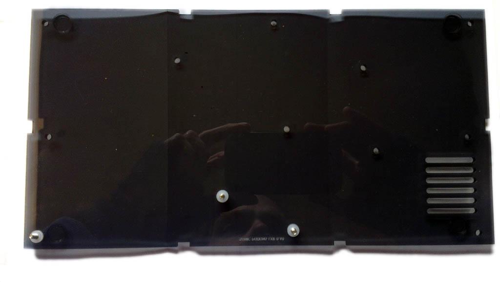
The lasercut bits may still be inside the backpanel. You can simply push them out.


Now you can assemble the rest of the enclosure with the new backpanel. Just follow the instructions for the regular enclosure assembly guide